
How this came to be:
I originally came across the TEC (Talking Electronics Computer1) while researching how to load home-brewed Gameboy ROMs onto bootleg carts. I found BennVenn’s Joey-Jr. on my quest and found it to be one of the best pieces of equipment I’ve ever used. Naturally, I returned to his website2 to browse and see what other goodies I could add to the arsenal. Near the bottom of the site I saw the magic words “Vintage Computer Gear” and dove right in. The were only 3 entries but one of them immediately caught my eye, the “TEC-1D Talking Electronics Z80 trainer computer”. Every vintage computer enthusiast has their favorite machine and favorite processor that they will irrationally defend to the death like a sports team. Mine happen to be the Altair 8800(and Imsai 8080) and the Z80 CPU respectively. The discerning amongst you might point out that both the Altair and Imsai don’t have Zilog CPUs but Intel. We are not rational actors here. Anyway, the TEC-1D had my brain doing cartwheels. I had to know more.


Evidently this machine was part of the computer trainer craze of the 80s and the platform that BennVenn learned how to code for the GB and GBC! I also wanted to gain a better understanding of the GB, so a quick purchase of the unpopulated PCB for less than the price of lunch was an easy choice. I had most of the parts on hand anyway, and got around five Z80 CPUs before the shutdown of their production in 20243 (RIP to a real one). After about a week and a half of shipping from good ol’ Aussieland I had the PCB in my hands and stayed up well into the morning soldering (around 5 of those hours were spent troubleshooting my EEPROMs). It eventually came to life and I had a grand time entering in the machine code for Big Ben Chimes and Quick Draw as laid out in the TE Magazine4 . It’s always cool when a circuit sings you a little song.
After about and hour I wanted to lay down and continue typing in programs from the comfort of my bed rather than hunched over my work bench like a gargoyle. So I picked up the machine and realized “Oh this thing needs to stay plugged in”. Well that’s not very conducive to leisurely development! I had to remedy this immediately. So I pulled out a 9v battery and rubberbanded it to the side. This worked for a few minutes but the TEC-1D is HUNGRY for current and quickly drained the 9v. Like any good engineer I decided to add a shit ton of overhead to the next iteration. Wanted to naturally increase the capacity of the cells but also figured bumping up the voltage couldn’t hurt either because 9 volts was right at the bottom the recommended voltage range. I grabbed a handful of spare 18650s and a charge controller I had laying around and slapped together a 12v power rechargeable battery with a barrel jack for DC charging. Also added a wonderful new innovation to the project called an on/off switch. This worked very well, and greatly expanded my runtime.
The Oopsie:

Then the ADHD hit, I placed my TEC-1D on a display shelf, and forgot about it until the bug bit me again. Seems like the turnaround on that was ’round-a-bout a year. I took the computer off the shelf, read the voltage with a multimeter, and thousand yard stared at the reading. Our 12v supply was hovering at around 4.4 Volts. A death sentence for these batteries. I tried trickle charging and brief over-volts but nothing seemed to get the pack beyond 4.89v. It was then I realized a crucial design flaw: I had directly soldered the cells to each other and to the controller. What I should have done is make sockets for each of the batteries so that they could be removed from the system when sitting for a long time, as well as just general serviceability.
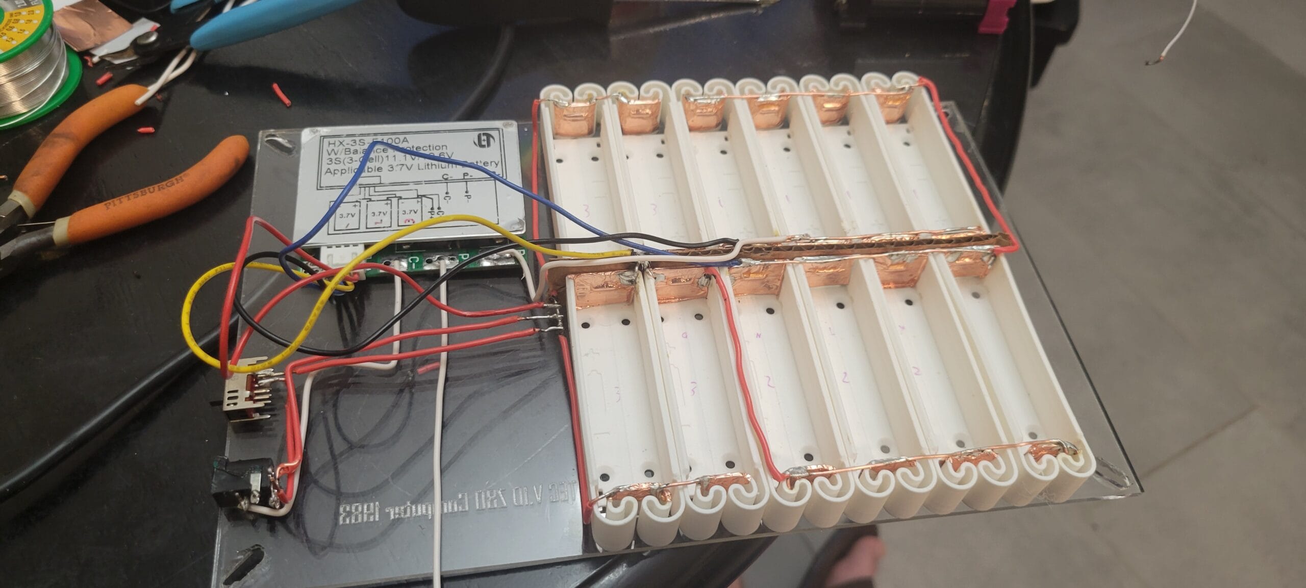
So here is my current solution, instead of double sided taping the cells and controller to the bottom of the PCB like a crackhead, I mounted them onto the original acrylic base I made for the TEC. I also tidied up the wiring and replaced my thinner junk wire with chunky, solid core, copper. I combined copper tape and 3D printed PLA 18650 sockets I found on Thingiverse5 and produced on the Bambu X1 Carbon I have at my day job, to create the removable solution we needed. After that all we needed was new batteries, luckily when it comes to 18650’s, between my friends who vape and past projects, my cup runneth over.


Planned features:
Honestly I thought this project was done but the Muse called Scope-Creep is whispering sweet nothings in my ear and I am already working on version 3 in my head as I type this. This battery pack needs 3-6 things to be *𝓅𝑒𝓇𝒻𝑒𝒸𝓉*.
A. It needs a battery level indicator. I personally am a fan of 5 level LED indicators if percentages aren’t available. I could whip up a percentage indicator with a microcontroller but honestly it just feels like a waste of power and money. 5 levels from 100% to 75%, 75% to 50%, 50% to 25%, 25% to 10%, and a 10% emergency charge indicator. In order to conserve power, the power indicator should only illuminate upon user request via a push button with the exception of the emergency charge indicator which should remain off until the power drops below 10% where it should then illuminate regardless of user input.
B. A fuse for over current protection. Honestly I should probably put a fuse on every cell but that may be in V4.
C. A temperature sensor to either turn on a cooling fan or, at a critical level, shut down the whole machine.
D. A quick connect polarized plug so I can quickly connect the pack to actual TEC.
E. A physical mount to the TEC, so like a way to mate the enclosures. Though I might just connect them psudo-permanently via brass standoffs.
F. A cooling fan for the cells though this is really optional. If they are running hot enough for a fan something else is wrong. Actually i might scratch this.
All In All:
I’m very excited to see this come together, especially with all the planned features. I will post and update soon as It is up and running!
Until next time,
-Cryo
Leave a Reply